
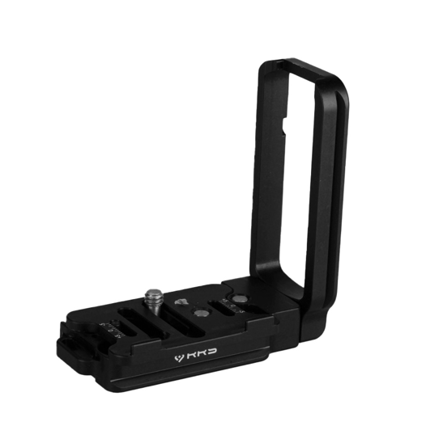
Overview
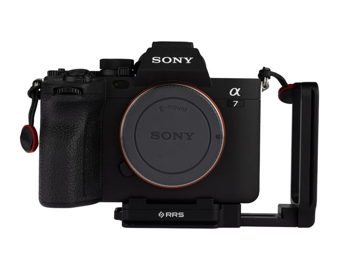
The MC-LS (SKU RRS-9000194) is a universal L-set, designed to be adaptable to a wide range of camera bodies. This manual will help you understand the function, assembly, and use of your MC-LS.
Section 1 - PARTS
In the Box:
- MC-LS Plate
- MC-LS Base Plate
- MC-LS Anti-twist Flange Plate
- MC-LC1 L-Component for MC-LS
- MC-LC2 l-Component for MC-LS
- 3x B107 1/4"-20 screw
- 1x 1/4"-20 x 3/16" flathead screw
- 1x 5/32" custom hex key
- 1x 5mm Safety Stop screw
- 1x 2.5mm Hex Key
______________________________________________________________________________________
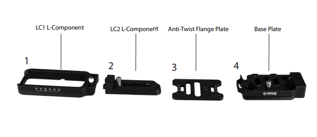
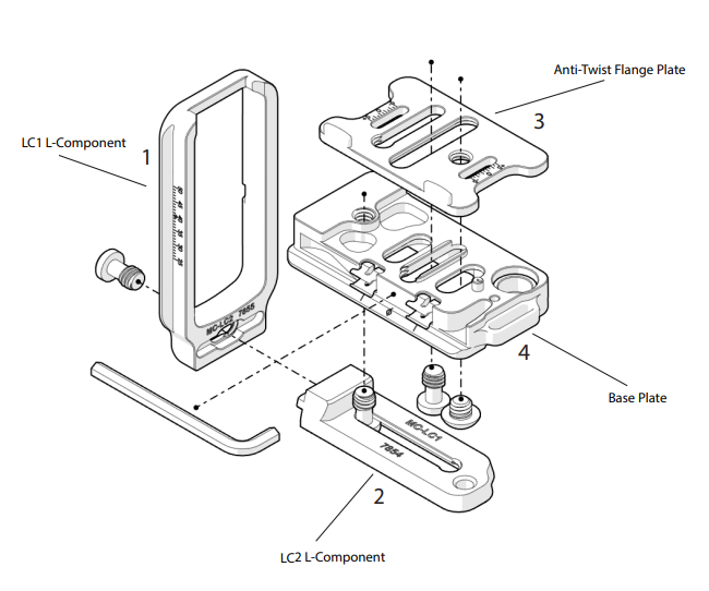
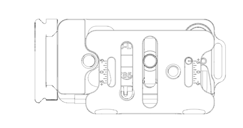
Section 2- PIECES AND LOCATIONS
The MC-LS is made up of four parts that go together like so:
- LC1 L-Component
- LC2 L-Component
- Anti-twist Flange Plate
- Base plate
______________________________________________________________________________________
Section 3- STEPS TO ASSEMBLE
Step One: Connect the Anti-Twist Flange Plate to the Base Plate with a 1/4"-20 x 3/16" flathead screw (the only different screw) using our 5/32 Hex Key
- Note: the 5/32 Hex Key is attached to the base plate with grippers rather than magnets. This does not affect the structural integrity.

Step Two- Use a B107 Screw, on the base of the LC1 to connect it to the LC2 for a complete L component.
Step Three- Connect the completed L component to the base plate, to make the L set using another B107 screw.
______________________________________________________________________________________
Section 3- STEPS TO ADJUST THE PLATE TO YOUR CAMERA
Each piece is adjustable, to make a flush fit for your camera!
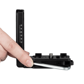
-To take the hex key out, press down on the protruding end, then it will pop right out! 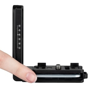
Step One- Extend your L component by loosening the first screw at the base of the L bracket to gain access to the other screws.
Step Two- Adjust the anti-twist flange onto the edge of your camera using the 1/4"-20 x 3/16 screw and the hex key. 
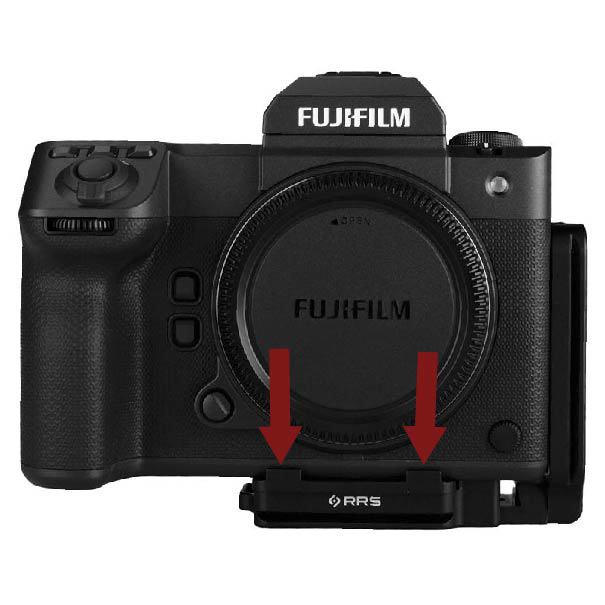
Step Three- Use the B107 screw located in the center of the base plate to attach the MC-LS to your camera.
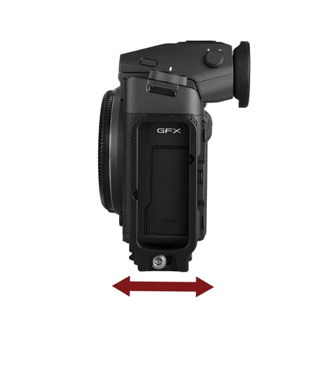
Step Four- Adjust the full L component (LC1 and LC2 together) by bringing it either forward or backwards so you have complete access to ports.
- Note: Sliding the L component forward and backwards will help accommodate the location of the side ports for different cameras and stiff cables that need more room.
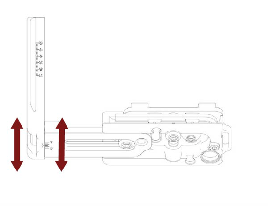
Step Five- Adjust the full L component (LC1 and LC2) until it fits flush against the side of your camera.
- Note: Extending the L component away from the side of your camera is to accommodate for easier access to ports and screen articulation.
To extend: loosen the first B107 screw at the very bottom of the plate. 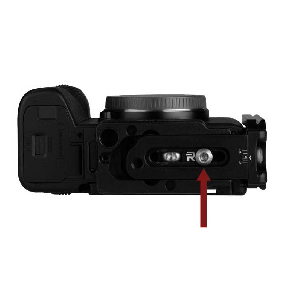

______________________________________________________________________________________
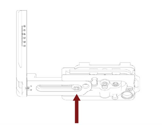
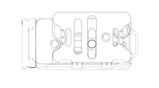
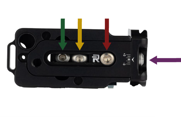
Section 4- SCREWS
Green Arrow: Screw that connects the MC-LS to your camera.
Yellow Arrow: Screw that connects the base plate to the Anti-Twist flange plate.
Red Arrow: Screw that connects the L component to the base plate.
Purple Arrow: Screw that connects LC1 to LC2.
-(If you switch the flange plate around, the location of the green and yellow arrow will change)
For any further questions, reach out to our customer service representatives at support@reallyrightstuff.com or call us at 385-248-0777