For a PDF version Click Here
WELCOME
Thank you for purchasing a Really Right Stuff tripod or monopod. Many years ago, we set out to create tripods that would exemplify the best in craftsmanship and quality. We are proud to present the results of that pursuit. Our 'pods are the culmination of first-hand experience and abundant input from seasoned professionals. Building upon our reputation of high precision CNC manufacturing, we enlisted unsurpassed composite manufacturing talent to bring you what we feel is a carbon fiber masterpiece. We sincerely hope you take a moment to appreciate this beautiful piece of equipment and review this manual to see how you can get the most from your tripod or monopod. If you have any questions or comments, please contact us. We love hearing your feedback.
Thanks again, and enjoy.

Really Right Stuff
720 S 850 E, Lehi, UT 84043
Phone: 1-385-248-0777 or toll-free US/CA 1-888-777-5557
Email: info@ReallyRightStuff.com
Web: www.ReallyRightStuff.com
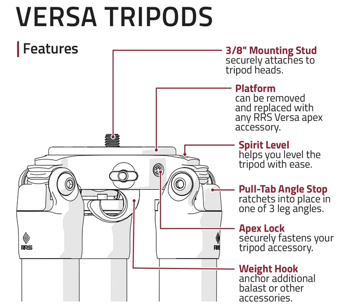
Universal Features
Tripod Accessories
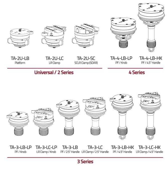
Leveling Bases
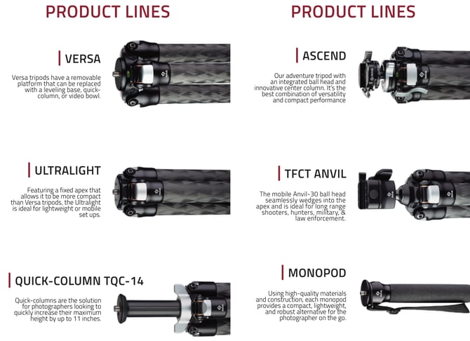
A leveling base on your tripod is the perfect foundation for gimbalheads, pano gear, and even ball heads. Each leveling base offers ±15-20° of leveling capability and locks solidly. Choose a leveling base with a flat platform (PF) for direct mounting of a tripod head. Or choose a leveling base with a clamp if you want quick-change convenience for multiple tripod heads on the same tripod.
General Tripod Use
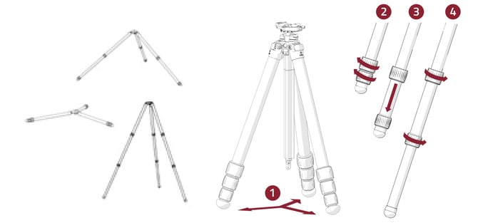
Leg Set Up
1. Swing out all three legs.
2. Grab twist locks with one hand, rotate one quarter turn to loosen.
3. Pull leg until fully extended.
4. Tighten Twist Locks.
5. Repeat on all legs.
6. To collapse, loosen twist locks and collapse leg. Grab all Twist Locks with one hand and tighten.
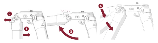
Set Leg Positions
1. Swing leg slightly inward.
2. Pull out tab completely (push closed at any time to cancel).
3. Swing leg to horizontal position. Angle stop will engage.
4. Move to desired position. Angle stop will ratchet automatically.
General Care
Maintenance Tips
When exposing your tripod to mud, sand, or saltwater, use a damp towel to wipe down and dry the legs completely before collapsing.
Then, disassemble and clean tripod per instructions on the next page.
Leg bolts should be tight enough to prevent legs from collapsing, but loose enough to open with ease. Use hex key to make adjustments as necessary.
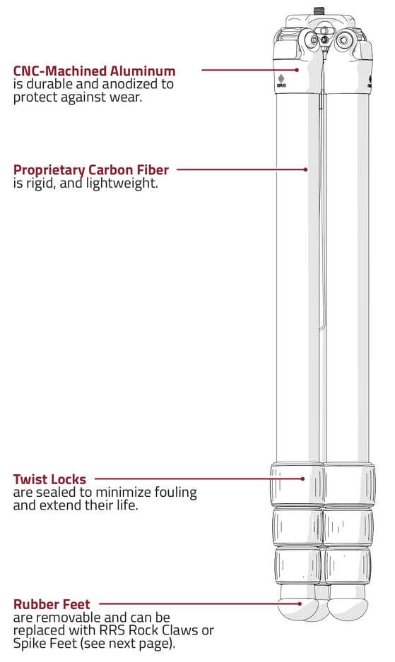
Periodically apply multi-purpose lubricant to the threads of each leg section twist lock. However, never lubricate the carbon fiber legs.
Check for metal corrosion. Contact Really Right Stuff for any necessary replacement parts.
Always keep your tripod in a protective bag when transporting or storing.
Always fully extend the lower leg section during use in sand or mud to prevent contaminating leg joints.
Cleaning
1. Rinse exterior with fresh water and towel dry.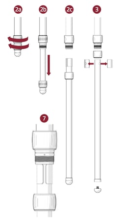
2. Unscrew twist lock and fully remove leg section.
3. Remove twist lock, foot, and anti-twist sleeves.
4. Wipe down leg, foot, and exposed threads with damp cloth, removing any dirt or debris. Allow to dry.
5. Apply small amount of multi-purpose grease to exposed leg threads.
6. Replace anti-twist sleeves and twist lock.
7. Holding anti-twist sleeves in place, insert leg into tripod where the arrow meets with gap between the anti-twist sleeves. Slide leg in completely.
8. Screw Twist Lock and foot back into position. Rotate Twist Lock back and forth to spread grease.
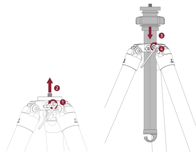
Changing Apex Accessories
Note: Apex Accessories are only available for Versa Tripods. Your tripod head should first be removed from the mounting stud/platform.
1. Use provided 5/32" hex key to loosen all three SureGrip set screws around Apex. Two rotations are sufficient, complete removal is not required.
2. Remove Apex platform or other accessory by pushing it upward.
3. Insert compatible accessory. NOTE: Although Gitzo® Systematic accessories will fit Versa Series 3 tripods, SureGrip functionality is only compatible with Really Right Stuff brand accessories.
4. Tighten all three SureGrip set screws.
Accessory Tip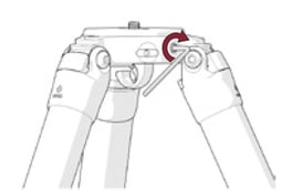
Check SureGrip set screws for proper tightness to ensure the Apex accessory is secure. Use provided hex key to make adjustments as necessary.
Ultralight Tripods
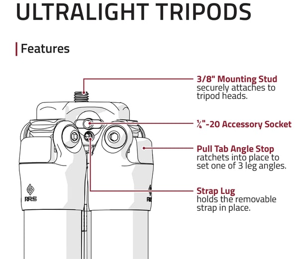
Adjust the Set Screw
Note: If you tighten the set screw, you will likely mar the bottom of your tripod head. To semi-permanently install your tripod head and avoid using set screws, use one drop of blue or medium strength threadlocker fluid on the stud when you install your head.
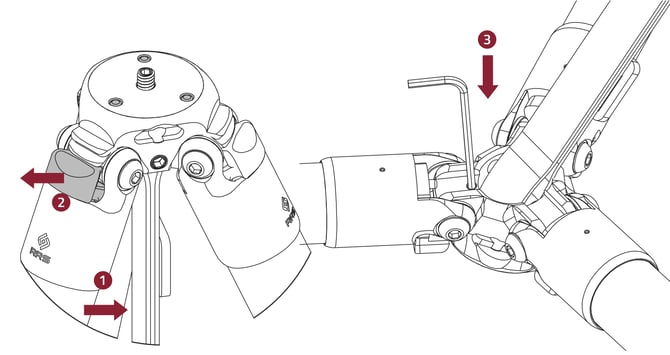
1. Swing leg closest to set screw inward slightly.
2. Pull Angle Stop out until it stops, then swing leg completely out.
3. Insert 2.5mm hex key into set screw from bottom side of tripod, then turn clockwise to tighten it against the bottom of your tripod head.
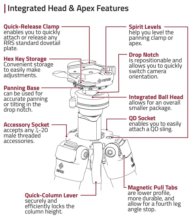
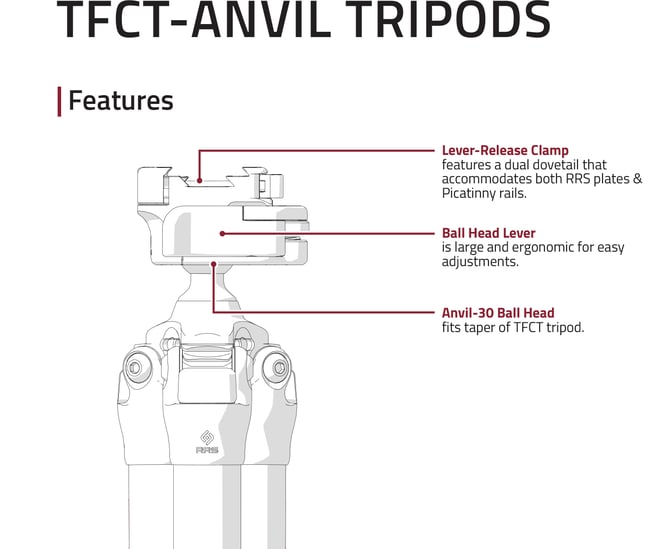
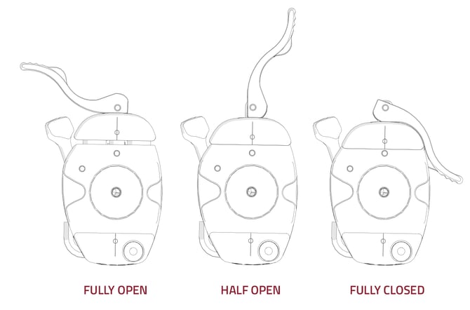
Quick-Release Clamp
1. Open lever to the FULLY OPEN position to top-load your quick- release plates.
2. With your quick-release plate engaged in the clamp, flip the lever to the HALFWAY OPEN position. Your plate freely slides in the clamp, but cannot be lifted out. Use the laser-engraved index marks on the jaws for precision positioning.
3. The stainless steel lever gives a positive “snap” when FULLY CLOSED with a plate engaged. This gives assurance that the plate was properly loaded and locked in place. In the closed position, the lever closely hugs the contours of the clamp.
Hex Key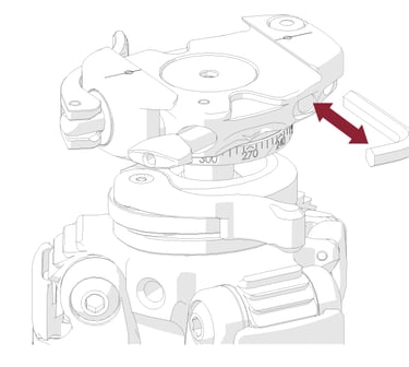
A custom 5/32” Hex Key is included with the tripod and stored in the clamp.
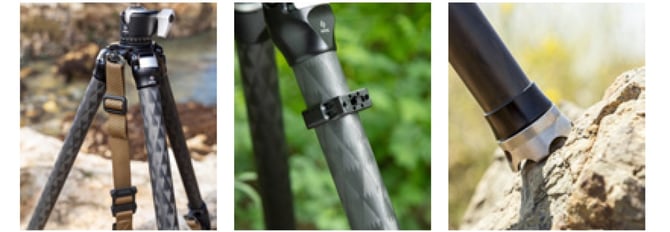
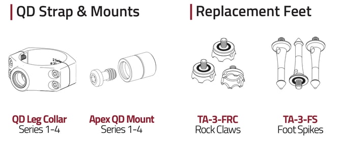
Optional QD Strap & Leg Collar
 Carry your tripod easily with a QD strap and QD leg collar (sold separately).
To attach a QD swivel, depress the button on the QD swivel and insert it into the QD socket. To release the QD swivel, press the same button and pull.
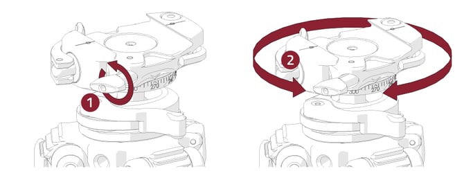
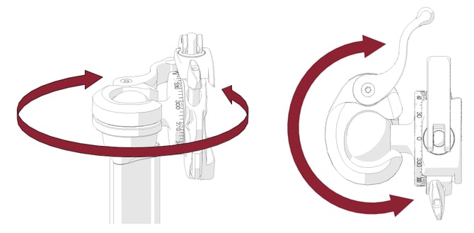
Panning Base
1. Loosen the panning lock knob
2. Pan left or right and tilt up or down using the markings for accurate adjustments
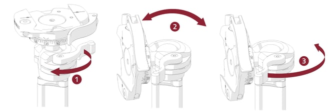
Ball Head & Drop Notch
1. Rotate the ball lock lever to loosen the ball head.
2. Move the ball head to your desired position. Lower the head into the drop notch to shoot vertically.
3. Rotate the ball lock lever to lock the head in place.
Reposition Drop Notch
When the ball lock lever is loosened, the entire head can be rotated. This allows the drop notch to be positioned in any location.
Re-time Lock Lever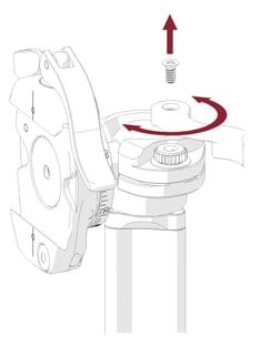
Lock lever tension is factory set, but can adjusted by the user if needed.
1. Lower the clamp into the drop notch.
2. Using a T9 Torx Key, loosen the screw on the ball lock lever.
3. Relocate the ball lock lever to desired position.
4. Carefully replace the screw (tighten to 4 in-lbs max).
 Platform Option
Head Installation
1. Screw the head onto the 3/8"-16 stud.
2. Tighten the set screw from below the platform. with the 1/8 hex key.
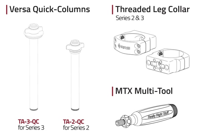
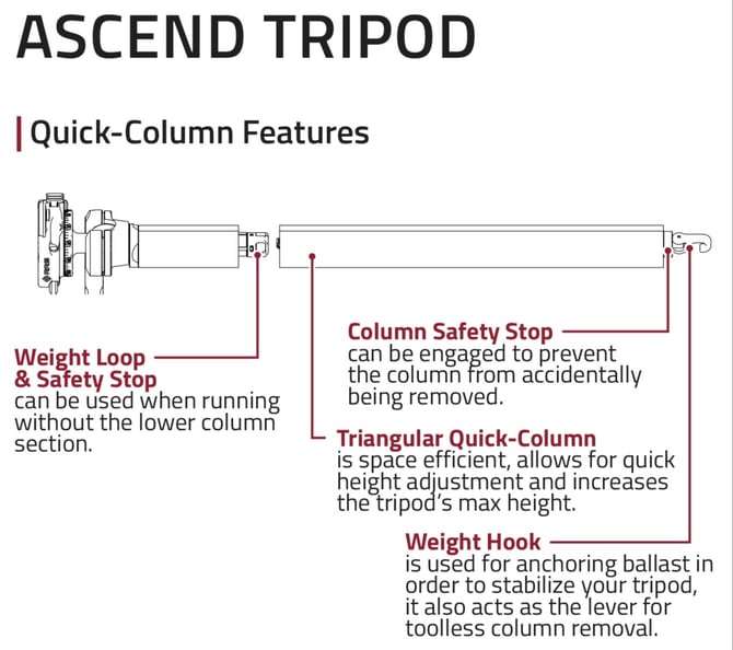
Raise Quick-Column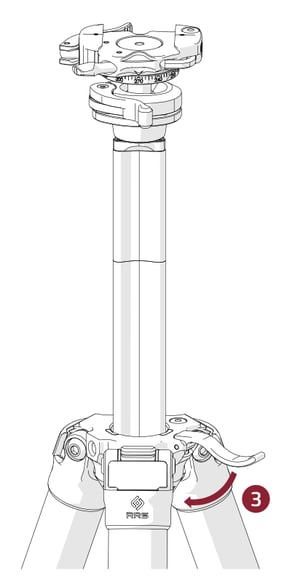
1. Lift the column lock lever to unlock the column.
2. Raise the column to desired height.
3. Lock the column in place by pushing lock lever back down.
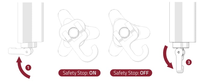
Quick-Column Safety Stop Details
Turning Safety Stop ON/OFF
1. Flip the hook perpendicular to the center column. This will loosen the tension on the safety stop. Unscrew the rod slightly if necessary.
2. Rotate the bronze piece 60 degrees to the ON or OFF position.
3. Flip the hook back down to tension the column.
NOTE: In the upper short section of the column is an additional safety stop that functions the same as the lower safety stop; rotate the gray triangular piece 60 degrees to turn the safety stop ON and OFF.
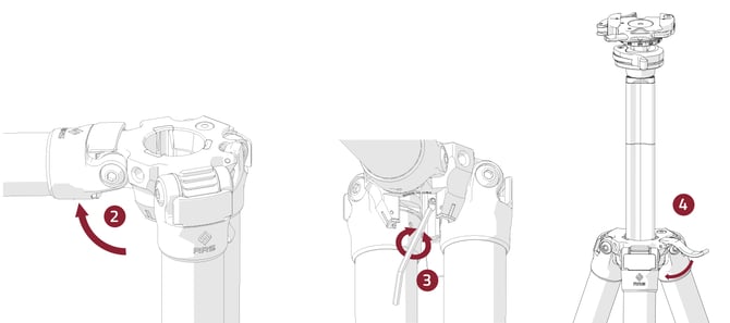
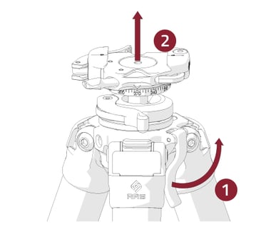
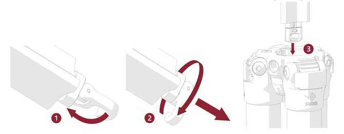
Detach Lower Section of Column
1. Turn safety stop to the OFF position if not already turned off (See Safety Stop Details), lift column lever lock, and remove column completely from apex.
2. Rotate the hook to release tension on the column
3. Rotate hook counter-clockwise until lower column completely separates and store aside.
4. Replace the upper column section into the apex.
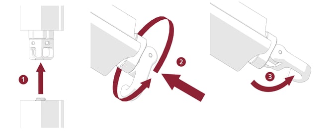
Reattach Lower Section of Column
1. Place lower column rod into the upper half of the quick-column.
2. While pushing the two column halves together, rotate the hook clockwise until you feel resistance.
3. Flip hook straight down to tighten column.
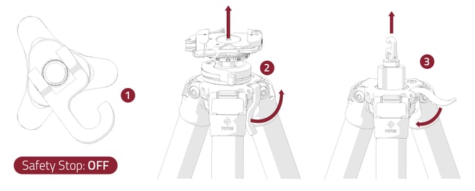
Reverse Quick-Column
1. Turn the safety stop to the OFF position if not already turned off (See Safety Stop Details).
2. Lift quick-column lever and remove column from apex (See Step 1 of Column Extension).
3. Replace the column from below the apex and lock the column. Ensure the load is secure.
4. Turn the safety stop to ON. (See Safety Stop Instructions).
Adjust Column Lock Tension
Column lock tension is factory set, but can adjusted by the user if needed.
1. Remove Column from apex (See: Raise Quick-Column)
2. Rotate the leg opposite of the column lever to the fourth position
3. Using the 3/32 hex key, turn the set screw through the hole in the plastic liner.
4. Test lock up by replacing the column and locking it. Repeat until desired tension is achieved.
NOTE: Only make up to ¼ turn hex key adjustments at a time.